A heat exchanger is a piece of equipment built for efficient heat transfer from one medium to another. The media may be separated by a solid wall to prevent mixing or they may be in direct contact. They are widely used in space heating, refrigeration, air conditioning, power plants, chemical plants, petrochemical plants, petroleum refineries, natural gas processing, and sewage treatment. The classic example of a heat exchanger is found in an internal combustion engine in which a circulating fluid known as engine coolant flows through radiator coils and air flows past the coils, which cools the coolant and heats the incoming air.
Flow arrangement
There are three primary classifications of heat exchangers according to their flow arrangement. In parallel-flow heat exchangers, the two fluids enter the exchanger at the same end, and travel in parallel to one another to the other side. In counter-flow heat exchangers the fluids enter the exchanger from opposite ends. The counter current design is the most efficient, in that it can transfer the most heat from the heat (transfer) medium per unit mass due to the fact that the average temperature difference along any unit length is higher. See Fig 4 countercurrent exchange. In a cross-flow heat exchanger, the fluids travel roughly perpendicular to one another through the exchanger.
For efficiency, heat exchangers are designed to maximize the surface area of the wall between the two fluids, while minimizing resistance to fluid flow through the exchanger. The exchanger’s performance can also be affected by the addition of fins or corrugations in one or both directions, which increase surface area and may channel fluid flow or induce turbulence.
The driving temperature across the heat transfer surface varies with position, but an appropriate mean temperature can be defined. In most simple systems this is the “log mean temperature difference” (LMTD). Sometimes direct knowledge of the LMTD is not available and the NTU method is used.
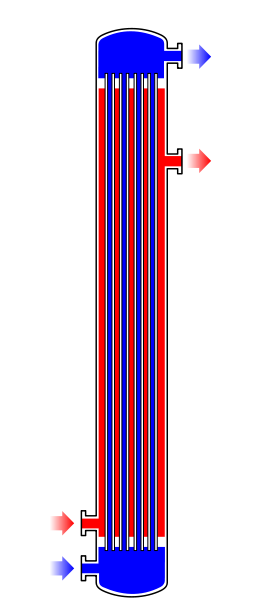
Fig. 1: Shell and tube heat exchanger, single pass (1–1 parallel flow)
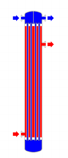
Fig. 2: Shell and tube heat exchanger, 2-pass tube side (1–2 crossflow)
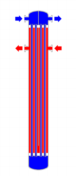
Fig. 3: Shell and tube heat exchanger, 2-pass shell side, 2-pass tube side (2-countercurrent)
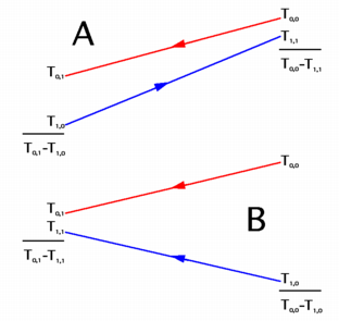
Fig.4: Countercurrent (A) and parallel (B) flows
Types of heat exchangers
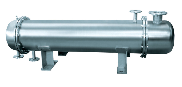
Shell and Tube heat exchanger
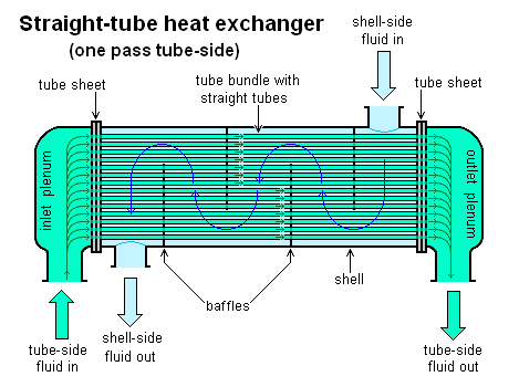 A Shell and Tube heat exchanger
Shell and tube heat exchangers consist of series of tubes. One set of these tubes contains the fluid that must be either heated or cooled. The second fluid runs over the tubes that are being heated or cooled so that it can either provide the heat or absorb the heat required. A set of tubes is called the tube bundle and can be made up of several types of tubes: plain, longitudinally finned, etc. Shell and tube heat exchangers are typically used for high-pressure applications (with pressures greater than 30 bar and temperatures greater than 260 °C).[3] This is because the shell and tube heat exchangers are robust due to their shape.
Several thermal design features must be considered when designing the tubes in the shell and tube heat exchangers: There can be many variations on the shell and tube design. Typically, the ends of each tube are connected to plenums (sometimes called water boxes) through holes in tubesheets. The tubes may be straight or bent in the shape of a U, called U-tubes.
- Tube diameter: Using a small tube diameter makes the heat exchanger both economical and compact. However, it is more likely for the heat exchanger to foul up faster and the small size makes mechanical cleaning of the fouling difficult. To prevail over the fouling and cleaning problems, larger tube diameters can be used. Thus to determine the tube diameter, the available space, cost and fouling nature of the fluids must be considered.
- Tube thickness: The thickness of the wall of the tubes is usually determined to ensure:
- There is enough room for corrosion
- That flow-induced vibration has resistance
- Axial strength
- Availability of spare parts
- Hoop strength (to withstand internal tube pressure)
- Buckling strength (to withstand overpressure in the shell)
- Tube length: heat exchangers are usually cheaper when they have a smaller shell diameter and a long tube length. Thus, typically there is an aim to make the heat exchanger as long as physically possible whilst not exceeding production capabilities. However, there are many limitations for this, including space available at the installation site and the need to ensure tubes are available in lengths that are twice the required length (so they can be withdrawn and replaced). Also, long, thin tubes are difficult to take out and replace.
- Tube pitch: when designing the tubes, it is practical to ensure that the tube pitch (i.e., the centre-centre distance of adjoining tubes) is not less than 1.25 times the tubes’ outside diameter. A larger tube pitch leads to a larger overall shell diameter, which leads to a more expensive heat exchanger.
- Tube corrugation: this type of tubes, mainly used for the inner tubes, increases the turbulence of the fluids and the effect is very important in the heat transfer giving a better performance.
- Tube Layout: refers to how tubes are positioned within the shell. There are four main types of tube layout, which are, triangular (30°), rotated triangular (60°), square (90°) and rotated square (45°). The triangular patterns are employed to give greater heat transfer as they force the fluid to flow in a more turbulent fashion around the piping. Square patterns are employed where high fouling is experienced and cleaning is more regular.
- Baffle Design: baffles are used in shell and tube heat exchangers to direct fluid across the tube bundle. They run perpendicularly to the shell and hold the bundle, preventing the tubes from sagging over a long length. They can also prevent the tubes from vibrating. The most common type of baffle is the segmental baffle. The semicircular segmental baffles are oriented at 180 degrees to the adjacent baffles forcing the fluid to flow upward and downwards between the tube bundle. Baffle spacing is of large thermodynamic concern when designing shell and tube heat exchangers. Baffles must be spaced with consideration for the conversion of pressure drop and heat transfer. For thermo economic optimization it is suggested that the baffles be spaced no closer than 20% of the shell’s inner diameter. Having baffles spaced too closely causes a greater pressure drop because of flow redirection. Consequently having the baffles spaced too far apart means that there may be cooler spots in the corners between baffles. It is also important to ensure the baffles are spaced close enough that the tubes do not sag. The other main type of baffle is the disc and donut baffle, which consists of two concentric baffles. An outer, wider baffle looks like a donut, whilst the inner baffle is shaped like a disk. This type of baffle forces the fluid to pass around each side of the disk then through the donut baffle generating a different type of fluid flow.
Fixed tube liquid-cooled heat exchangers especially suitable for marine and harsh applications can be assembled with brass shells, copper tubes, brass baffles, and forged brass integral end hubs.
Plate heat exchanger
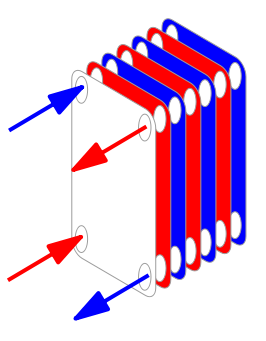 Conceptual diagram of a plate and frame heat exchanger.
Another type of heat exchanger is the plate heat exchanger. One is composed of multiple, thin, slightly separated plates that have very large surface areas and fluid flow passages for heat transfer. This stacked-plate arrangement can be more effective, in a given space, than the shell and tube heat exchanger. Advances in gasket and brazing technology have made the plate-type heat exchanger increasingly practical. In HVAC applications, large heat exchangers of this type are called plate-and-frame; when used in open loops, these heat exchangers are normally of the gasket type to allow periodic disassembly, cleaning, and inspection. There are many types of permanently bonded plate heat exchangers, such as dip-brazed, vacuum-brazed, and welded plate varieties, and they are often specified for closed-loop applications such as refrigeration. Plate heat exchangers also differ in the types of plates that are used, and in the configurations of those plates. Some plates may be stamped with “chevron”, dimpled, or other patterns, where others may have machined fins and/or grooves.
Pillow plate heat exchanger
A pillow plate exchanger is commonly used in the dairy industry for cooling milk in large direct-expansion stainless steel bulk tanks. The pillow plate allows for cooling across nearly the entire surface area of the tank, without gaps that would occur between pipes welded to the exterior of the tank.
The pillow plate is constructed using a thin sheet of metal spot-welded to the surface of another thicker sheet of metal. The thin plate is welded in a regular pattern of dots or with a serpentine pattern of weld lines. After welding the enclosed space is pressurized with sufficient force to cause the thin metal to bulge out around the welds, providing a space for heat exchanger liquids to flow, and creating a characteristic appearance of a swelled pillow formed out of metal.
Fluid heat exchangers
This is a heat exchanger with a gas passing upwards through a shower of fluid (often water), and the fluid is then taken elsewhere before being cooled. This is commonly used for cooling gases whilst also removing certain impurities, thus solving two problems at once. It is widely used in espresso machines as an energy-saving method of cooling super-heated water to use in the extraction of espresso.
Optimisation
There are three goals that are normally considered in the optimal design of heat exchangers: (1) Minimizing the pressure drop (pumping power), (2) Maximizing the thermal performance and (3) Minimizing the entropy generation (thermodynamic ). See for example:
Waste Heat Recovery Units
A Waste Heat Recovery Unit (WHRU) is a heat exchanger that recovers heat from a hot gas stream while transferring it to a working medium, typically water or oils. The hot gas stream can be the exhaust gas from a gas turbine or a diesel engine or a waste gas from industry or refinery.
Big systems with high volume and temperature gas stream, typical on industry, can benefit from Steam Rankine Cycle (SRC) in a WHRU, but small systems become too expensive to use it. The recover of heat from low temperature systems requires more efficient working fluids than steam.
An Organic Rankine Cycle (ORC) WHRU can be more efficient at low temperature range using Refrigerant that boil at lower temperatures than water. Typical organic refrigerants are Ammonia, Pentafluoropropane(R-245fa and R-245ca), and Toluene.
The refrigerant is boiled by the heat source in the Evaporator to produce super-heated vapor. This fluid is expanded in the turbine to convert thermal energy to kinetic energy, that is converted to electricity in the electrical generator. This energy transfer process decreases the temperature of the refrigerant that, in turn, condenses. The cycle is closed and completed using a pump to send the fluid back to the evaporator.
Dynamic scraped surface heat exchanger
Another type of heat exchanger is called “(dynamic) scraped surface heat exchanger”. This is mainly used for heating or cooling with high-viscosity products, crystallization processes, evaporation and high-fouling applications. Long running times are achieved due to the continuous scraping of the surface, thus avoiding fouling and achieving a sustainable heat transfer rate during the process.
Phase-change heat exchangers

Typical kettle reboiler used for industrial distillation towers

Typical water-cooled surface condenser
In addition to heating up or cooling down fluids in just a single phase, heat exchangers can be used either to heat a liquid to evaporate (or boil) it or used as condensers to cool a vapor and condense it to a liquid. In chemical plants and refineries, reboilers used to heat incoming feed for distillation towers are often heat exchangers.
Distillation set-ups typically use condensers to condense distillate vapors back into liquid.
Power plants that use steam-driven turbines commonly use heat exchangers to boil water into steam. Heat exchangers or similar units for producing steam from water are often called boilers or steam generators.
In the nuclear power plants called pressurized water reactors, special large heat exchangers pass heat from the primary (reactor plant) system to the secondary (steam plant) system, producing steam from water in the process. These are called steam generators. All fossil-fueled and nuclear power plants using steam-driven turbines have surface condensers to convert the exhaust steam from the turbines into condensate (water) for re-use.
To conserve energy and cooling capacity in chemical and other plants, regenerative heat exchangers can transfer heat from a stream that must be cooled to another stream that must be heated, such as distillate cooling and reboiler feed pre-heating.
This term can also refer to heat exchangers that contain a material within their structure that has a change of phase. This is usually a solid to liquid phase due to the small volume difference between these states. This change of phase effectively acts as a buffer because it occurs at a constant temperature but still allows for the heat exchanger to accept additional heat. One example where this has been investigated is for use in high power aircraft electronics.
Heat exchangers functioning in multiphase flow regimes may be subject to the Ledinegg instability.
Check out the Heat Exchanger Introduction Video.