Tramming – Aligning the Milling Head
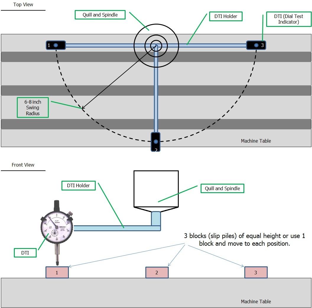
- Place the machine spindle about an inch (25mm) in from the back table edge.
- Using a DTI holder, set the DTI anywhere from 6″ to 8″ out from the spindle centre.
- Use 3 sets of blocks, or a similar gauge block to slide under the DTI for each reading.
- Tighten the knee-lock clamp on the saddle.
- Adjust the swivel head in the X-axis to get zero readings at positions #1 and #2 (at about 1″ (25mm) in from the table edge). This will roughly align the head in the X-axis.
- Now swing the indicator to the #3 position, and adjust the knuckle joint in the Y-axis to get zero readings at positions #1 and #3. At this point the head is aligned quite close.
- Now go back and check positions #1 and #2, and adjust if necessary. check #1 and #3 again, adjust if needed.
- When all (3) positions read zero, (or within a total of .001″) the head is aligned in both axes.
NOTE:
With the indicator at the #3 position, loosen the knee-lock clamp and check the DTI reading. If the reading drops .003 or more, it’s time to tighten up the gib on the knee ways (but it’s always a good practice to tighten the knee-lock clamp when machining high accuracy cuts). When adjusting the swivel and knuckle, leave a little tension on the clamping bolts. This will help prevent the head from moving when you fully tighten these bolts
